

Download: Model No_ATC22K-380S380-W Specification
Download: Model No_ATC22K-380S540-W Specification
Download: Model No_ATC22K-380S640-W Specification

Download: Model No_ATC22K-380S380-W, ATC22K-380S540-W, ATC22K-380S640-W 3D Drawing
Download: TTC-BC-P01-0_Q&A_ATC22KC-380S380-W(Annren)_2025-11-11
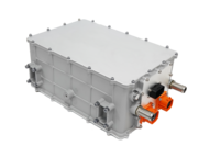
Features● Output Power:22KW
● Input Voltage:3 phase 304~456VAC 1 phase 175~265VAC
● Output Voltage:200~450 400~650 450~750VDC
● Dimensions:370x252x158mm
● Weight: ≤20KG
● Cooling System:Liquid
● Protection Level:IP67 (except fan)
● Communication Method:CAN
● Enclosure: Aluminum alloy made
● Software: Digital software design
| Item | Part Name | Model Name | Power (W) | Input Voltage (VAC) | Output Voltage (VDC) | Output Current (A) | Efficiency | Size (mm) | Cooling System | Weight (Kg) |
| 1 | 22KW OBC | ATC22K-380S380-W | 22000 | 3 phase 304-456 1 phrase 175-265 |
200~450 | 64 | ≥94% | 370x252x158 | Liquid | 20 |
| 2 | ATC22K-380S540-W | 400~650 | 46 | |||||||
| 3 | ATC22K-380S640-W | 450~750 | 40 |
Specification
| Description | Technical specifications | Remark | ||||||||||||||||||||||||||
| Environmental characteristics | Operating temperature | -40~85℃ | Long-time working | |||||||||||||||||||||||||
| Vibration/noise | Meet the QC/T 895-2011 standard | |||||||||||||||||||||||||||
| Salt spray experiment | Meet the QB/T 2423.17-2008 standard | |||||||||||||||||||||||||||
| Output Power | 22KW | |||||||||||||||||||||||||||
| Input voltage range | Three-phase 304~456VAC (line-to-line voltage, three-phase four-wire) Single phase 175~265VAC |
|||||||||||||||||||||||||||
| Output voltage range | 200~450/400~650/450~750VDC | |||||||||||||||||||||||||||
| Low voltage input auxiliary source | 13.8VDC(2Amax) | |||||||||||||||||||||||||||
| Activation method | PP/CP/hard wire | |||||||||||||||||||||||||||
| Voltage accuracy | ±1% | |||||||||||||||||||||||||||
| Output maximum current | Three phase: 56±2A, single phase: 20±2A | |||||||||||||||||||||||||||
| Voltage ripple factor | ≤±1% | |||||||||||||||||||||||||||
| Current accuracy | ±3% | Half load or more | ||||||||||||||||||||||||||
| Efficiency | ≥94% | Rated voltage Full load | ||||||||||||||||||||||||||
| Parallel function | Networking is performed by internal CAN communication, and up to 8 modules can be connected in parallel. | |||||||||||||||||||||||||||
| Output response time | The rise time of the output voltage of the car charger should be less than 300ms, and the overshoot should be less than 10%. After receiving the shutdown command, the current drops below 10% within 300ms and drops to 0A within 500ms. | |||||||||||||||||||||||||||
| Other protection features | Input overvoltage, input undervoltage, output overvoltage, output undervoltage, short circuit, output overcurrent, overtemperature, reverse connection protection, potential equalization and ground protection, power failure protection. | |||||||||||||||||||||||||||
| Over temperature protection | When the temperature reaches 85 °C, the output power is reduced by half. The temperature is <80 °C in 10 minutes, and the full load is automatically restored. After 10 minutes, the temperature is >80 °C, then it is turned off. When the temperature is >90 °C, it will be shut down directly. | |||||||||||||||||||||||||||
| CAN byte speed | 250Kbps/500Kbps | |||||||||||||||||||||||||||
| Dielectric strength | Output to the outer casing | 2000VDC /60S 10mA Max | ||||||||||||||||||||||||||
| Input to the outer casing | 1500VAC /60S 10mA Max | |||||||||||||||||||||||||||
| Input to output | 3000VAC /60S 10mA Max | |||||||||||||||||||||||||||
| Insulation resistance | Input to output | ≥20MΩ | ||||||||||||||||||||||||||
| Input to the outer casing | ≥20MΩ | |||||||||||||||||||||||||||
| Electromagnetic compatibility | Radiation emission | GBT 18387:2008,EN 55022 CLassB | ||||||||||||||||||||||||||
| Conducted emission | GBT 18387:2008,EN 55022 CLassB | |||||||||||||||||||||||||||
| Radiation immunity | GBT 18387:2008,EN 55022 CLassB | |||||||||||||||||||||||||||
Structural parameters
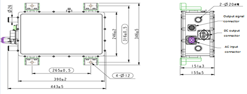
Connector information
| Position | Socket model | Function | Brand | Plug model |
| A | HVC4P36MV306 | AC input | Amphenol | HVC4P36FS306 |
| B | HVC2P60MV100 | DC output | Amphenol | HVC2P60FS3116 |
| C | RT001823PN03 | Control terminal | Amphenol | RT061823PNH03 |
Interface definition
| Socket definition | Pin number | Interface definition | Description | |||||||||||||||
| AC input HVC4P36MV306 |
1 | FireWire 1 | L1 (single fire line fixed input) | |||||||||||||||
| 2 | FireWire 2 | L2 | ||||||||||||||||
| 3 | FireWire 3 | L3 | ||||||||||||||||
| 4 | N | Neutral/midline | ||||||||||||||||
| A | Interlock 1 | Connection interlock 5 | ||||||||||||||||
| B | Interlock 2 | Connection interlock 3/micro switch | ||||||||||||||||
| N | Ground wire | Product enclosure | ||||||||||||||||
| DC output HVC2P60MV100 |
1 | positive electrode | Output positive | |||||||||||||||
| 2 | negative electrode | Output negative | ||||||||||||||||
| A | Interlock 3 | Connection interlock 2/micro switch | ||||||||||||||||
| B | Interlock 4 | Connection interlock 6 | ||||||||||||||||
| Control terminal RT001823PSN03 |
A | CAN1-L | CAN low | |||||||||||||||
| B | VCC+ | Normal input | ||||||||||||||||
| C | VCU_EN | Hard-wire wake-up OBC, enable signal (active high) | ||||||||||||||||
| D | CP | CP | ||||||||||||||||
| E | PP | PP | ||||||||||||||||
| F | WAKE_UP | VCU/BMS wake-up signal (1A) Isolated from input constants |
||||||||||||||||
| G | NTC1- | Temperature sensor 1 negative | ||||||||||||||||
| H | NTC1+ | Temperature sensor 1 positive | ||||||||||||||||
| J | NTC2- | Temperature sensor 2 negative | ||||||||||||||||
| K | NTC2+ | Temperature sensor 2 is positive | ||||||||||||||||
| L | CAN1-H | CAN high | ||||||||||||||||
| M | LOCK+ | Electronic locks | ||||||||||||||||
| N | LOCK+ | Electronic locks | ||||||||||||||||
| P | LOCK feedback | Electronic locks | ||||||||||||||||
| R | CP_OUT | CP status output, low level enable | ||||||||||||||||
| S | Interlock 5 | Interlock signal detection 1 | ||||||||||||||||
| T | Interlock 6 | Interlock signal detection 4 | ||||||||||||||||
| U | NC | NC | ||||||||||||||||
| V | TB_R | Terminal resistance selection, short circuit to C pin, the resistance is effective | ||||||||||||||||
| W | NC | |||||||||||||||||
| X | CAN2-L | Internal parallel CAN2 low | ||||||||||||||||
| Y | CAN2-H | Internal parallel CAN2 high | ||||||||||||||||
| Z | EN2 | Internal parallel enable (reserved) | ||||||||||||||||